Centrifugal fan development in the United Kingdom

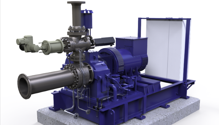
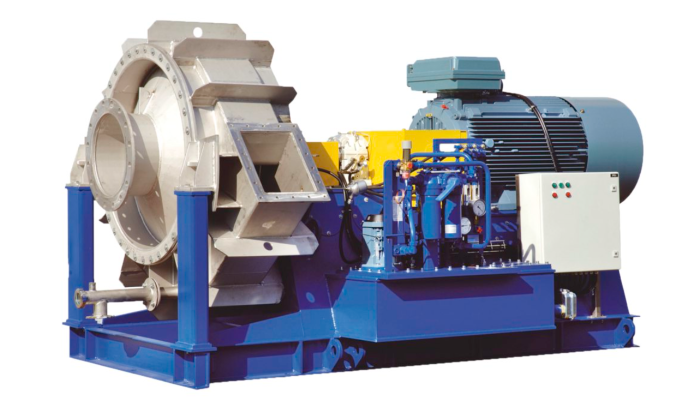
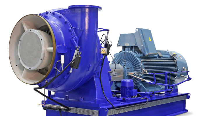
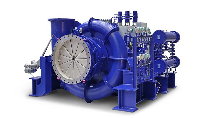
In the UK, Howden has a long history of developing and innovating solutions on industrial fans. One such innovation has been in the area of centrifugal fans running at variable speed. From our base in Renfrew, United Kingdom we have researched and engineered solutions that ensure the health of centrifugal fans operating with variable speed drives. Howden have devised a stringent set of rules for the assessment of fans. Each fan is designed to ensure it complies with our acceptance criteria for:-

  • static stress
  • fatigue
  • dynamics
  • rotordynamics

Finite Element Analysis is a widely used design tool in this process.

Howden are experts in the design of rotating machinery and have the technical knowledge and experience to assess whether a switch to variable speed operation is structurally acceptable for a customer's operating requirements.

Printable PDF/brochure including fan laws and fan speed
Centrifugal fan development in UK

Variable Speed Drive installation

Howden would recommend the following before implementing a variable speed drive retrofit:

  • Checking the actual operating duties of the existing fans to ensure they would not be in stall or an unsuitable part of the fan curve.
  • Check the bearings and auxiliary equipment to ensure they are suitable for variable speed operation.
  • Check the foundations are suitable and there is no coincidence between foundation and fan natural frequencies (critical speed) in the operating range.
  • Calculate impeller fatigue life under variable speed control. This will require a finite element analysis. Note with an older constant speed fan the life could be considerably reduced by using variable speed control and new impellers may be required.
  • Carry out either a bump test of the existing impeller or an engineering analysis to determine impeller natural frequencies and ensure no dynamics problems.
  • NDT existing impellers. Where fitted, this will require removal of wear liners to give access to structural welds. Any cracks would require proper repair and NDT. After inspection / repair, fit new wear plates and re-balance. Although possible on site it may be easier (lower cost) to carry out these steps in a Howden factory.

Summary – After VSD Installation

  • Check fan balance
  • Refine / determine actual exclusion speeds for the individual fan installation, if applicable
  • Approximately 3 months after the fan is back in normal service it should be NDT checked for cracks and thereafter on an annual basis, as a minimum


Case Study: L3N Sinter Fan

Variable speed drives were fitted to Waste Gas Sinter Fans in a steelworks and the operating regime changed. Instead of running at constant speed these fans were now running with several speed changes per day.

Soon after the change to variable speed, a routine inspection of the fan flagged numerous cracks at weld toe positions, some up to 50mm in length.

In addition full thickness cracks were noted at the centreplate cutaways, as shown in the photograph and image in figure 1.

The depth and extent of the cracking observed resulted in the fan being deemed unsafe to use and immediately taken out of service.

Howden were asked to carry out a Finite Element Analysis of the original fan and to design a replacement which would be suitable for variable speed operation.

The analysis of the original impeller showed it had acceptable structural integrity for constant speed operation. This had been demonstarted by its actual service life to date (over 20 years of start/stops).

However, an area of relatively high stress at the root of the centreplate cutaway was noted, as shown in the following plots. This was consistent with the location of the cracks found during inspection.

cracks in centrifugal fan

Figure 1


cracks in centrifugal fan

Figure 2

The estimated fatigue life for the fan, following convertion to variable speed operation was calculated to be only a few months. This hence confirmed that this fan was not suitable for variable speed operation.

The analysis was repeated for a new impeller design, This incorporated several modifications, including changes to weld specifications and to the cutaway dimensions and location.

Changes were also introduced to minimise the impeller inertia, thus allowing it to run on the existing supports and with the previously used motor.

The results confimed the following for the new design:-

  • Static Stress Levels were acceptable.
  • A fatigue life could be achieved to comply with the customer’s variable speed operating requirements. This data was presented to the customer in the form of a Miner’s summation, detailing combinations of start/stops and various speed change cycles.
  • The impeller natural frequency analysis complied with design rules.
  • The rotordynamics gave acceptable results over the full running speed range and complied with critical speed assessement criteria.


Get full article - including fan laws document

Read the full article which includes fan laws and fan speeds.

Email Address
First Name
Last Name
Company
Country


If you would like to submit an enquiry please get in touch.