
Howden
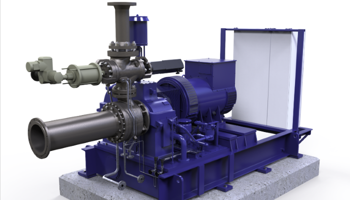
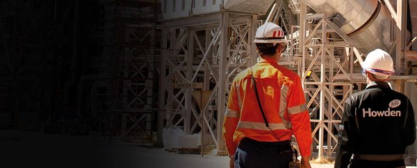
Howden provides mission critical air and gas handling products and services, that our customers’ vital processes depend on. We help our customers to increase their environmental and operational efficiencies and to decarbonize their operations. We are advancing a more sustainable future.
We are Howden
Revolving Around You
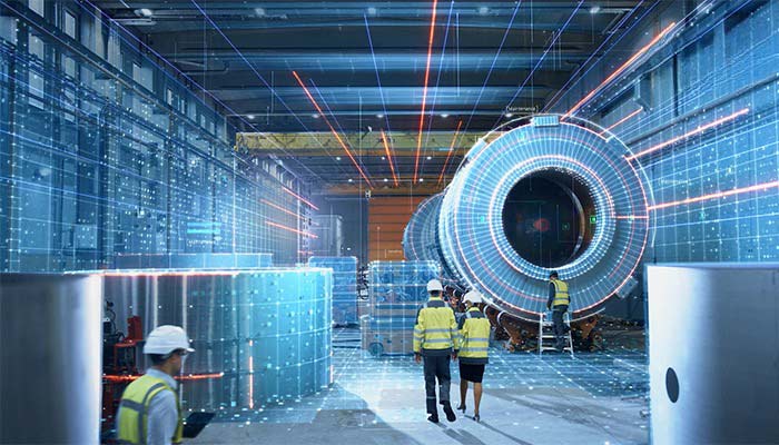
For over 160 years, Howden, has been at the forefront of developing engineered solutions for the needs of industrial processes. Today our technology and worldwide engineering expertise and services optimise our customers' vital processes throughout the world. This is ensured through a strong global network of experts, formed from responsive local service and delivery teams, in more than 100 countries, who are familiar with local requirements and challenges.
The latest chapter of our history is as a Chart Industries company, having been acquired in 2023. The strategic combination of both companies expands our offering of products and solutions across the Nexus of Clean™ - clean power, clean water, clean food and clean industrials. The complementary nature of the equipment and solution portfolios results in a differentiated offering across many industries benefitting customers by enabling a more complete solution to their operational and engineering needs.
Video Library

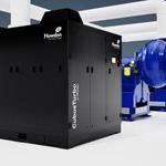
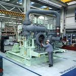

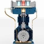
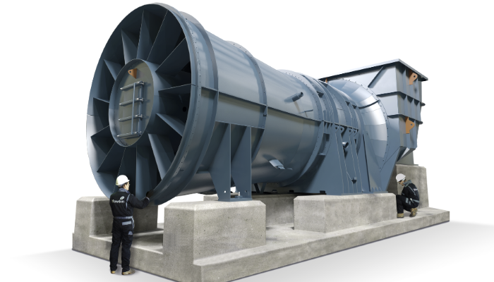
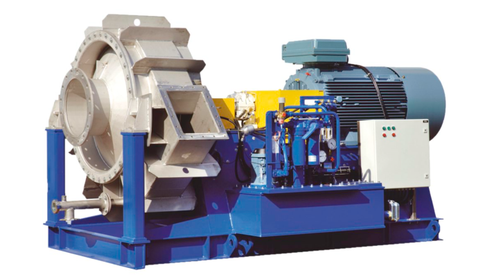
Product & Brand Portfolio
Use the carousel below to navigate straight to our principal product pages. Continue to scroll to learn more about our business.


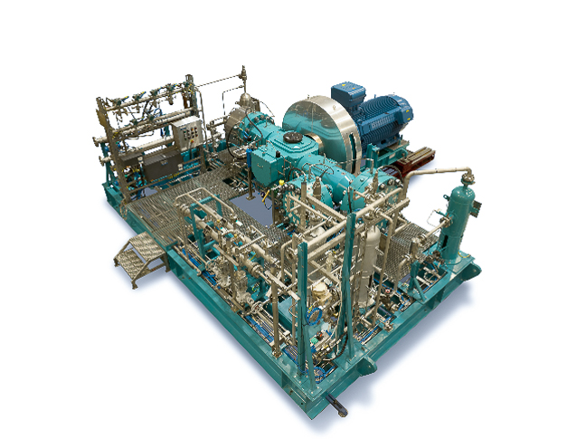
Burton Corblin
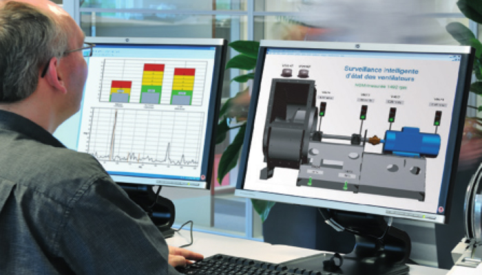
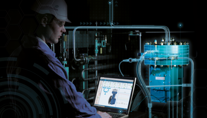
Aftermarket
Howden has developed the unique 4P (Parts, Presence, Precision, Prevention) concept to deliver faster and higher productivity with continuous technological innovation. That means quality products, training, and services designed and tailored to meet each custumer’s needs.
We offer Outage Solutions that bring together a wide range of technical expertise we reduce complexity, identify optimized scope solutions, and deliver within the tightest of timescales. With careful planning and risk management, we can avoid lost revenue by reducing the risk of future plant failure, maximising component life, and restoring and improving plant performance.

}
Howden ESG
ESG is integrally linked to our vision of ‘enabling our customers’ vital processes which advance a more sustainable world’, and is clearly aligned with one of our core values, ‘we do the right thing’. In short, our ESG efforts are a fundamental characteristic of our brand as well as our purpose as an organisation.

Technical Library
View and download solutions brochures for some of our major markets.
Contact Howden
To send an enquiry, submit an RFQ, find our locations or join our team, click the Contact Us button.General Enquiries +44 141 885 7500


 Request A Quote
 Email An Inquiry
 Find Our Locations
 Join Our Team